THE ELECTRIC CURRENT THEORY
Table of contents
- Introduction to Electricity
- The Atomic Structure
- Conductors
- Insulators
- The Electric Current
- Resistors and Resistance
- Measuring Instruments
- Resistor Colour Codes
______________________________________________________________________
- Introduction to electricity
What is electricity? Electricity is a flow or movement of current, and what does the term current means? Current is movement of electrons from one point to another or current is flow of electrons in one direction. This exlpanation will be discussed in details at a later stage.
___________________________________________________________
2. The Atomic Structure
Click on the picture below to enlarge it.
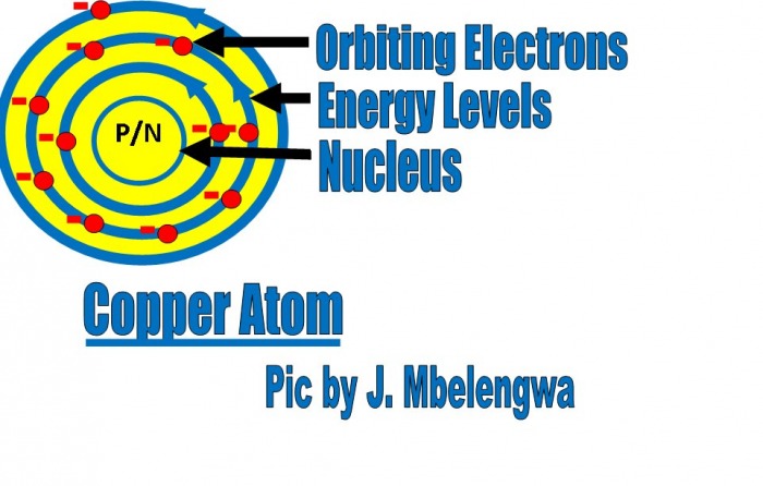
An atom is the smallest component of an element having the chemical properties of the element. It consists of orbiting electrons, energy levels or electron shell and nucleus. The nucleus consists of protons and neutrons (P/N). Protons are positively charged and neutrons are neutral. An electron is an elementary particle with negative charge(see orbiting electrons on the above picture). The number of electrons in an atom is equal to the number of protons, therefore any normal atom is electrically neutral. If an atom losses an electron it will have more protons than electrons, therefore it will be positively charged. If an atom gains or accept an electron it will have more protons than electrons, therefore it will be negatively charged. Copper atom has 11 electrons and 11 protons. - The first energy level contains 2 electrons, the second 8 electrons and the last energy level contains 1 electron. The formula of calculating the number of electrons in an energy level is 2(n)3. Where n represent the number of energy level i.e. 1st energy level, 2nd energy level etc. The number of electrons in the first ,second and third energy levels of for an example copper is 2, 8 and 1 respectively. For more relevant information on how to calculate the maximum number of electrons that are contained in one electron shell, Click here.
Now that you understand the structure of copper atom, we will now tackle copper material as a conductor of electricity. Copper is a good conductor of electricity becaause it has free electrons.. This free electrons will become delocalised from the copper atom (see the above picture) by exposing copper conductor to a mere room temperature. It is this free electrons that constitude current when the conductor is connected to a power supply.
_____________________________________________________________________________________
3. Conductors
A conductor is any material in which free electrons can easily flow or a conductor is a material with many free electrons. The free electrons in a conductor can be caused to move freely in a particular direction when a battery or any other electrical source of supply is connected across its ends (see the picture below). Examples of conductors are:-
- Copper
- Aluminium
- Silver
- Gold
- Iron
- Brass
- Steel
- Graphite
- Carbon
- Mercury
- Dirty Water
- Concrete
- Bronze
_______________________________________________________________________
4. Insulators
An insulator is any materal that does not easily allow current to flow. Examples of conductors are:-
- Plastic
- PVC
- Glass
- Rubber
- Oil
- Asphalt
- Porcelain
- Ceramic
- Quartz
- Dry cotton
- Pure Water
- Dry Wood
- Air
________________________________________________________________________________
5. The Electric Current
Click on the picture below to enlarge it.
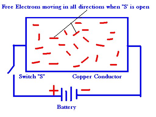
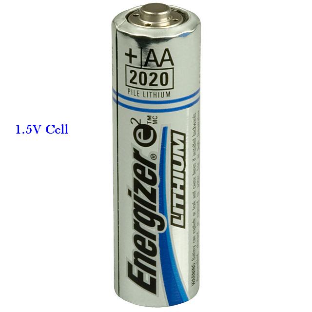
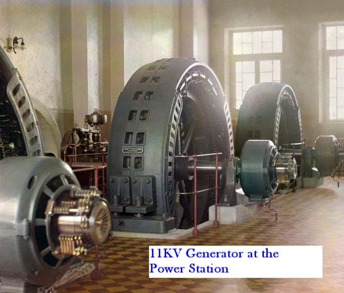
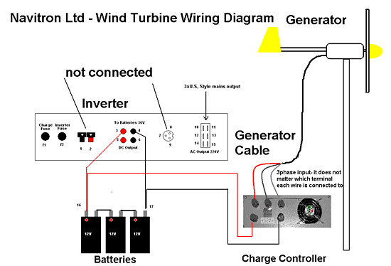
when the switch is open delocalised electrons (free electrons) will move in all directions. If the swich is closed, negative terminal of the battery will repel the negative ions that are in the copper conductor. The repelled negative ions will be attrated by the postive terminal of the battery. Inside the batterry these electrons will move from positive terminal to negative terminal. The electrons which were moving in all directions are now moving externally from negative terminal to the positive terminal of the battery. Hence the electrons are now moving in one direction.When the electrons are moving from one point to another or in one direction,they are called current. What causes these electrons to flow in one direction? In order for the current to flow there must be a closed circuit and a source of power supply must be part of that closed loop. The power supply in the above diagram is the battery. Batteries, cells and generators are nothing else but electrical pumps. They pump electricity because of their electrical pressure that are found in them. They are ones that are responsible for forcing the electrons to move from the negative terminal to the positive terminal of the battery. Voltage can thus be described as electrical pressure and is measured in volts (V).
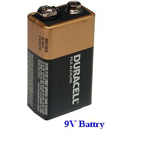
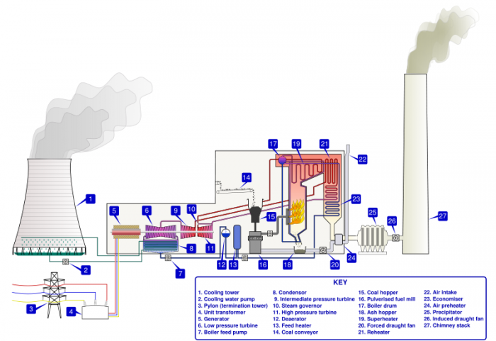
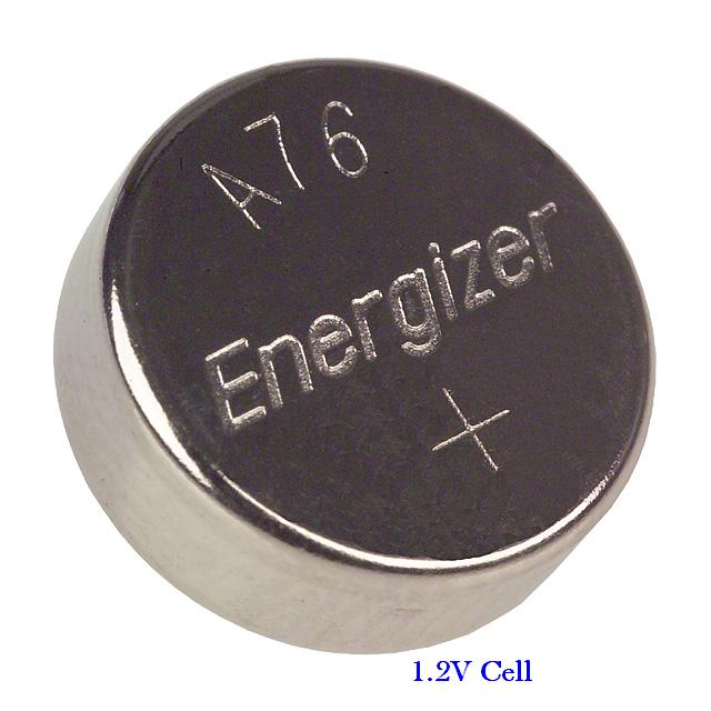
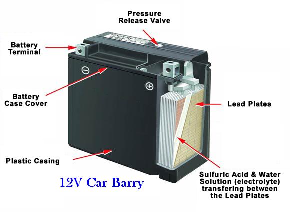
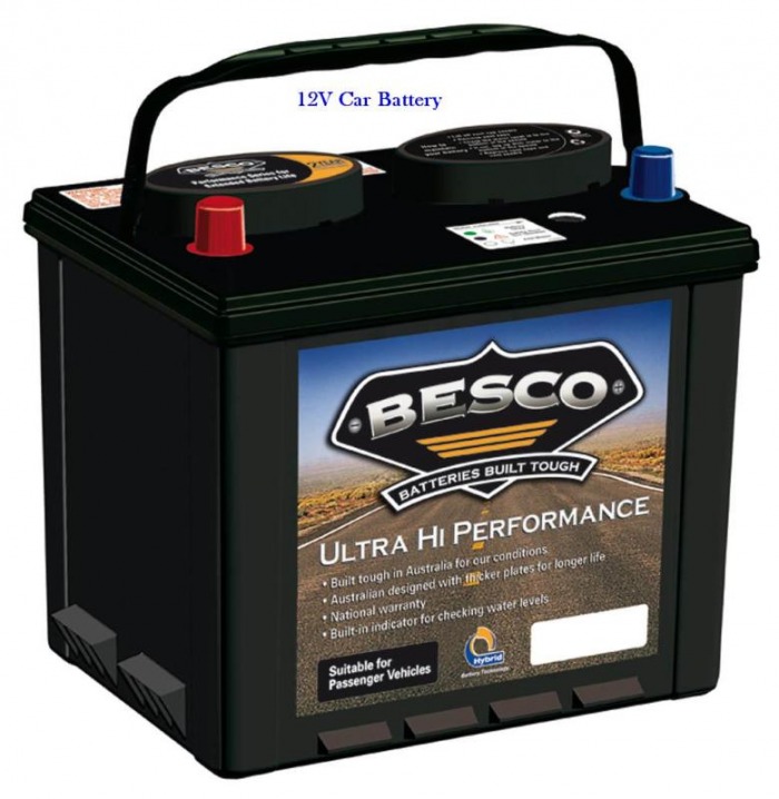
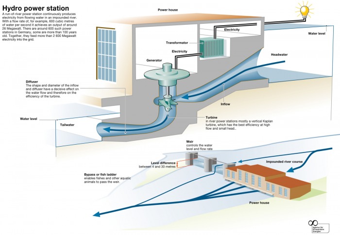
Bellow are the picture of different types of power supplies:- Click on any of the picture to view slides.
Bellow are the picture of different types of power supplies:- Click on any of the picture to view slides.


__________________________________________
6. Reisistors and Resistance
Click on the picture below to enlarge it.
A resistor is a two terminal electronic or electrical device that resist the flow of current.They are made of various compounds, resistor wires (an alloy of nickel and chrome) and films. The primary features of resistors are the resistance, the tolerance, the rating power and the maximum working voltage.
Resistance is the ability of a resistor to oppose the flow of current and it is measured in ohms(Ω). Resistors are elements of electrical and electronic circuits and are found in most electronic equipments. For example,
- radios
- TV's
- computers
- cell phones
- calculators
- CD Players
- alarm systems
- cars
- VCR's
Click hereto learn more about resistors.
________________________________________________________________________
7. Measuring Instruments
An electrical measuring instrument is a calibrated transducer which registers an electrical quantity. The oscillocope is the only measuring instrument which displays the maximum peak to peak voltage magnitude, whereas all other electrical test intruments indicate the root mean square(R.M.S.) magnitude.A voltmeter is electrical measuring instrument that measures volage.
- A voltmeter is electrical measuring instrument that measures volage. It has a very high resistance and it is always connected across or in parallel.
- An ammeter is an electrical or electronic device that mesearues the flow of current. Unlike the voltmeter, it has a very low resistance (negligeble resistance)
- computers
- cell phones
- calculators
- CD Players
- alarm systems
- cars
- VCR's
Click here to learn more about resistors.
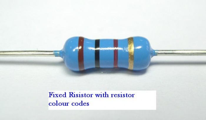
8. Resistor Colour Coding
The values of most fixed resistors are shown by a guide of coloured bands. Three or four of are spaced fairly close together to the one end. In the case of a four colour band fixed resistor first ring indicate the first whole number of the resistance value, the second band represent the second whole number and the third band signifies the multiplier or number of zeros should be added to first two digits. The fourth whole number stand for tolerance. When they are only three colours, the tolerance is 20%.
In the case of a five colour band fixed resistor first ring indicate the first whole number of the resistance value, the second band represent the second whole number, the third band signifies the third whole number of the resistance value, fourth band symbolizes the multiplier or number of zeros that should be added to the last number of the first three whole numbers. the fifth number stands for tolerance.
___________________________________________________________________________
The resistor colour codes are well illustrated by the chart below:-
Scroll through the resistor colour code table to view it clearly.
Download the file below to do Resistor Colour Code Assessment 1:-
| 26840734-resistor-colour-code-assessment-1.pdf |
